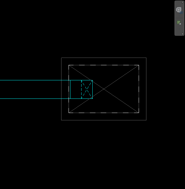
[Solved] Revit does not display vertical elbows (i.e., risers in shafts) properly in plan view
Let’s talk a little about Plan Regions in Revit. In a nutshell, this tool helps to show areas of a View that may need to deviate from your view’s View Range. Aside from the common uses for this in architecture, mechanical designers can actually get their risers to display properly when using a vertical elbows.
The Problem
Mechanical and plumbing Revit Designers have undoubtedly run into issues with their ducts that turn vertically if the elbow is outside of the view’s View Range. Revit does not cut through the elbow properly, if it cuts through it at all. Note the image below is missing the “X” within the riser to graphically designate which system the duct is on.
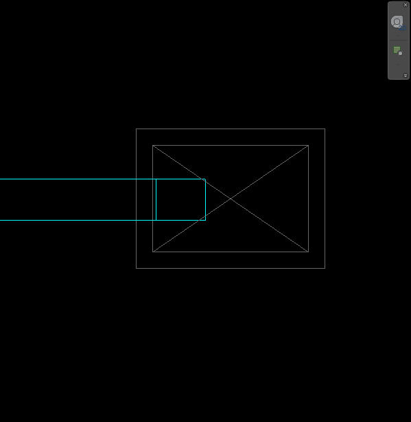
The issue is caused by the View Range settings for your view. Don’t fuss with the View Range settings for the entire View because tweaking View Range for one riser can be catastrophic for your the rest of the elements on your View.
The Solution: Use a Plan Region
The steps below outline a simple workflow to fix this issue. The goal is to create a Plan Region that encompasses the shaft’s view range requirements. Note that this technique also works with pipe elbows that do not graphically show the proper up or down symbol.
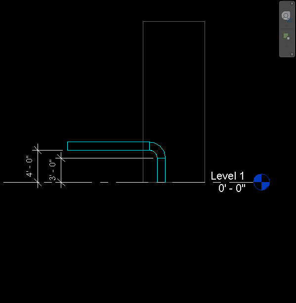
First, take note of the elevations that you need where you need to adjust your view range for the Plan Region.
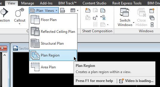
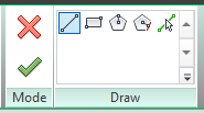
Next, go to View > Plan Region and draw a shape around the area you would like the View Range to effect.
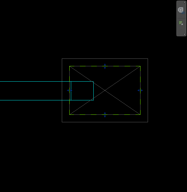
Important: Your plan region needs to encompass the entire riser for this to work. If the outline of your Plan Region overlaps the duct, it will not be effected.
You may want to extend your Plan Region a little further out than the duct itself. Note that the Plan Region outlines do not print.
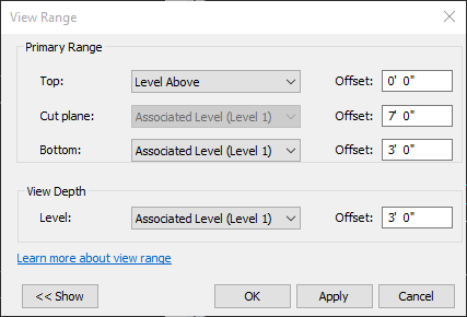
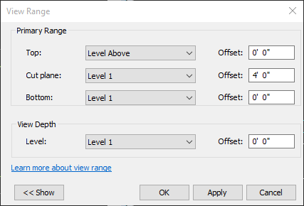
Now we must adjust the View Range for the Plan Region. With the outline of the Plan Region selected, go to the View Range setting in the Properties window.
Adjust your View Range accordingly based on your measurements from step one.
The riser should now display the appropriate symbology within the duct that is turning up or down.
